I did this on my 99 Camaro with the monsoon system. This should work on all 98+ monsoon systems. I followed the steps Jason gave on LS1Tech.com. I give all credit to him. I am just posting this over here on camarov6.com. These are the pics and how I did it.
What you need:
-http://www.radioshack.com/product/index.jsp?productId=2103451&cp (the headphone jack)
-A cord to connect the headphone jack of the mp3 played headphone jack to the stereo connection....audio cable. http://shopping.yahoo.com/p:Cables%2...zB_sorQHwbFt0A something like this
-22 or 20 gauge wire, 4 sections about 3-4 feet long, different colors.
-Solder
-Soldering Iron
-Electrical tape
-Sharpie
-Wire Strippers
-Drill
-5/64" drill bit........Smaller Bit
-15/64" drill bit.......Medium Bit
-21/64" drill bit.......Larger Bit
First step Remove Deck:
-Pull of the main faceplate, removing the wires attached for the SGS and Fog lights on the faceplate.
-Remove the two screws holding the deck in place.
-Pull the deck out, removing the antenna cord, power cord, and the other cord.
-The deck should slide right out.
Next Remove the the cover plate on the Deck:
-Flip the deck upside down. This is the plate you have to remove.
-Remove the two screws on the back and one on the top.
Begin the mod:
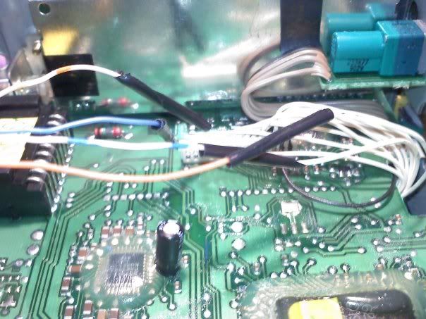
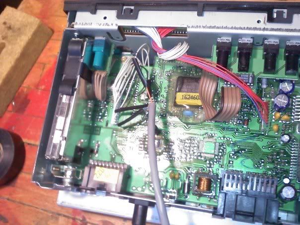
-Locate the cd connector, it is the white strip with white wires attached.
-The wire in Pin1, going from right to left, is the left channel. The wire in Pin3 is the right channel.
-Take the sharpie mark the Pin1 wire with one line close to the base, then about 2 inches down that same wire put another line. Then for the wire in Pin3 put three lines close to the base then again about 2 inches down on the same wire put three lines. This helps keep track of which wire is which after they are cut.
-Cut the Pin1 wire exactly halfway in between your markings. Then repeat for the wire in Pin3.
-Then cut the black wire exactly halfway in length.
(I'll be using the colors based off of the ones I used.)
-Refer to the pin diagram in the pictures provided, for the next six steps, some pictures were from Jason's write up.
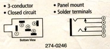
-Take the headphone jack solder your green ground wire to Pin1 of the jack.
-Attach the solid blue wire to Pin2.
-Attach the blue/white wire to Pin3.
-Attach the solid orange wire to Pin4.
-Attach the orange/white wire to Pin5.
-Check all leads to make sure none can ever possible touch.
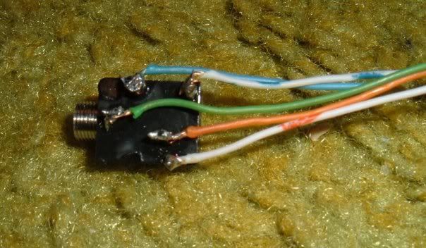
Connect wires to deck:
-Now we refer back to the cd connector in the deck for Pin#.
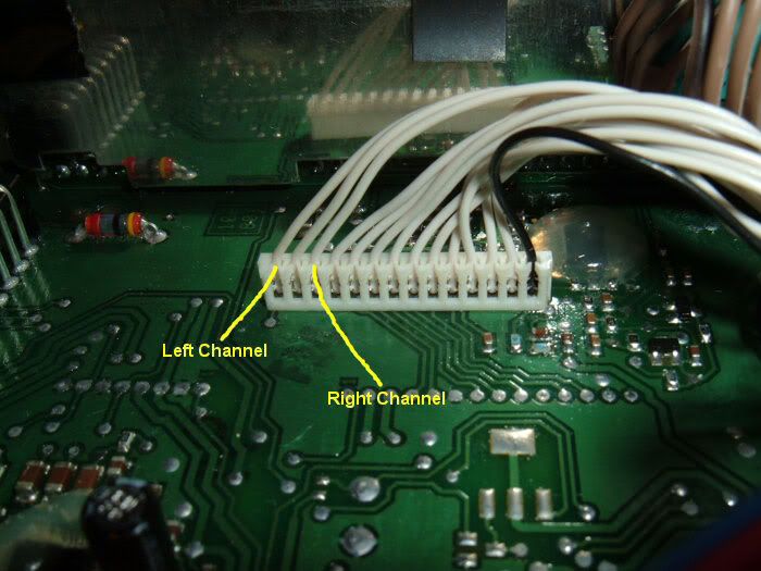
-The solid blue wire connects to Pin1 coming from the white cd connector.
-The orange/white wire connects to Pin3 coming from the white cd connector.
-The blue/white wire connects to the Pin1 coming from the underside of the board.
-The solid orange wire connects to the Pin3 coming from the underside of the board.
-Connect the green wire to the black wire, solder all three wires together(the 2 black and the 1 green).
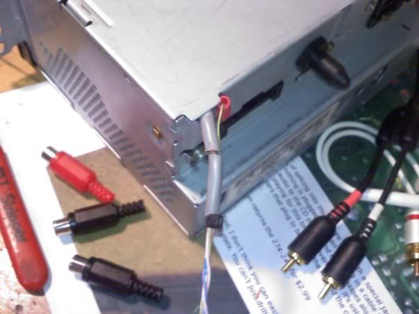
-Route the wires out the back of the deck through one of the holes that is just the right size to fit through. (Refer to the pictures of how I did it).
-Put the cover back on and replace the screws.
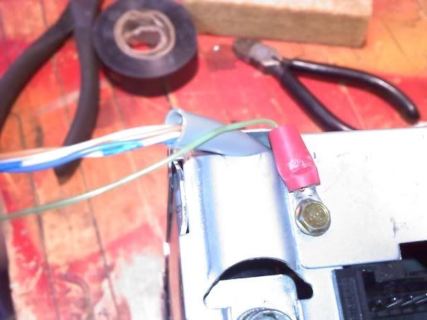
(Side note, I stated above to route the green wire to the black wire as ground, in this pic i hooked it to the screw as ground, either way its grounded. Either way it works)
Put back in car:
-Take the wires and route them out the back of the dashboard, you will be able to see the gas pedal, route the wires out to there.
-Put the deck back in, be careful no wires get pinched or cut in half, put screws back in.
-Reattach the cover, attaching the SGS and Fog light wires.
-Put the faceplate back on.
Next step is routing it into the center console:
-Put car in neutral.
-Open lid of console, remove the two screws holding the top plate of the center console in place.
-Lift up take the wires route them underneath the console through the back of the console
-Tape it to the side of the console so it doesn't interfere anywhere.
-This is a crucial part, if you drill wrong you will have to re-drill and it won't look as nice.
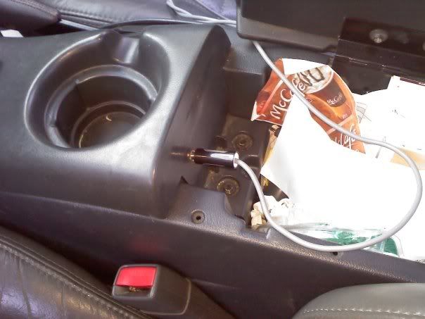
-Take a the smaller drill bit to cut a pilot hole in the console. If you go too low the jack will not fit in the back. (Refer to picture for the placement i put mine in, works freely so the lid does not come in contact with it.)
-Next take the medium drill bit, drill all the way through.
-Now be **EXTREMELY CAREFUL HERE** take the larger drill bit and drill roughly halfway through......DO NOT GO ALL THE WAY THROUGH!!!!
-Take the nut off of the jack.
-Put the jack through the hole, put the nut back on, and tighten it
-Tape any loose tape to wall of console.
-Replace the console, put screws back in.
-Put car back in park.
Test it:
-Turn car on, put a cd in the drive
-The car will only play the ipod if a cd is in the cd drive. You must press the cd button.
-Don't attach the audio cable yet.
-Check to see if the cd player is playing, it should be.
-Now attach the audio cable to the mp3 player and the headphone jack.
-Now the deck should be playing the mp3 player.
If after this it doesn't work, repeat all steps and make sure everything is done correctly. If everything is done correctly, pm me or post on here. If you follow all of the directions precisely the mod will look like a factory option and clean.
If I left anything out let me know I'll fix it, or if anything isn't clear enough let me know. Again I give all credit to Jason, I just did the mod and put it on here for the cv6 community.
Jason's Link:
http://www.ls1tech.com/forums/stereo...t-adapter.html
What you need:
-http://www.radioshack.com/product/index.jsp?productId=2103451&cp (the headphone jack)
-A cord to connect the headphone jack of the mp3 played headphone jack to the stereo connection....audio cable. http://shopping.yahoo.com/p:Cables%2...zB_sorQHwbFt0A something like this
-22 or 20 gauge wire, 4 sections about 3-4 feet long, different colors.
-Solder
-Soldering Iron
-Electrical tape
-Sharpie
-Wire Strippers
-Drill
-5/64" drill bit........Smaller Bit
-15/64" drill bit.......Medium Bit
-21/64" drill bit.......Larger Bit
First step Remove Deck:
-Pull of the main faceplate, removing the wires attached for the SGS and Fog lights on the faceplate.
-Remove the two screws holding the deck in place.
-Pull the deck out, removing the antenna cord, power cord, and the other cord.
-The deck should slide right out.
Next Remove the the cover plate on the Deck:
-Flip the deck upside down. This is the plate you have to remove.
-Remove the two screws on the back and one on the top.
Begin the mod:
-Locate the cd connector, it is the white strip with white wires attached.
-The wire in Pin1, going from right to left, is the left channel. The wire in Pin3 is the right channel.
-Take the sharpie mark the Pin1 wire with one line close to the base, then about 2 inches down that same wire put another line. Then for the wire in Pin3 put three lines close to the base then again about 2 inches down on the same wire put three lines. This helps keep track of which wire is which after they are cut.
-Cut the Pin1 wire exactly halfway in between your markings. Then repeat for the wire in Pin3.
-Then cut the black wire exactly halfway in length.
(I'll be using the colors based off of the ones I used.)
-Refer to the pin diagram in the pictures provided, for the next six steps, some pictures were from Jason's write up.

-Take the headphone jack solder your green ground wire to Pin1 of the jack.
-Attach the solid blue wire to Pin2.
-Attach the blue/white wire to Pin3.
-Attach the solid orange wire to Pin4.
-Attach the orange/white wire to Pin5.
-Check all leads to make sure none can ever possible touch.

Connect wires to deck:
-Now we refer back to the cd connector in the deck for Pin#.

-The solid blue wire connects to Pin1 coming from the white cd connector.
-The orange/white wire connects to Pin3 coming from the white cd connector.
-The blue/white wire connects to the Pin1 coming from the underside of the board.
-The solid orange wire connects to the Pin3 coming from the underside of the board.
-Connect the green wire to the black wire, solder all three wires together(the 2 black and the 1 green).
-Route the wires out the back of the deck through one of the holes that is just the right size to fit through. (Refer to the pictures of how I did it).
-Put the cover back on and replace the screws.

(Side note, I stated above to route the green wire to the black wire as ground, in this pic i hooked it to the screw as ground, either way its grounded. Either way it works)
Put back in car:
-Take the wires and route them out the back of the dashboard, you will be able to see the gas pedal, route the wires out to there.
-Put the deck back in, be careful no wires get pinched or cut in half, put screws back in.
-Reattach the cover, attaching the SGS and Fog light wires.
-Put the faceplate back on.
Next step is routing it into the center console:
-Put car in neutral.
-Open lid of console, remove the two screws holding the top plate of the center console in place.
-Lift up take the wires route them underneath the console through the back of the console
-Tape it to the side of the console so it doesn't interfere anywhere.
-This is a crucial part, if you drill wrong you will have to re-drill and it won't look as nice.
-Take a the smaller drill bit to cut a pilot hole in the console. If you go too low the jack will not fit in the back. (Refer to picture for the placement i put mine in, works freely so the lid does not come in contact with it.)
-Next take the medium drill bit, drill all the way through.
-Now be **EXTREMELY CAREFUL HERE** take the larger drill bit and drill roughly halfway through......DO NOT GO ALL THE WAY THROUGH!!!!
-Take the nut off of the jack.
-Put the jack through the hole, put the nut back on, and tighten it
-Tape any loose tape to wall of console.
-Replace the console, put screws back in.
-Put car back in park.
Test it:
-Turn car on, put a cd in the drive
-The car will only play the ipod if a cd is in the cd drive. You must press the cd button.
-Don't attach the audio cable yet.
-Check to see if the cd player is playing, it should be.
-Now attach the audio cable to the mp3 player and the headphone jack.
-Now the deck should be playing the mp3 player.
If after this it doesn't work, repeat all steps and make sure everything is done correctly. If everything is done correctly, pm me or post on here. If you follow all of the directions precisely the mod will look like a factory option and clean.
If I left anything out let me know I'll fix it, or if anything isn't clear enough let me know. Again I give all credit to Jason, I just did the mod and put it on here for the cv6 community.
Jason's Link:
http://www.ls1tech.com/forums/stereo...t-adapter.html


Comment